Use multiview projection for view layout. C-Clamp Assembly Frame End Angle.
Assembly And Details
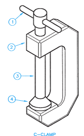
These clamps are called C clamps because of their C-shaped frame but are otherwise often called G-clamps or G-cramps because including the screw part they are shaped like an uppercase letter G.
. A locking clamp is a combination of a plier and a C-clamp. C-Clamp Assembly Screw Details of. For large tubes safety one accepts the long area of constriction.
Working drawing metric Assembly Name. The shaft ends are made to abutt each other and a single key is fitted directly in the keyways of both the shafts. Go to Article 3D CAD Models - C-clamp PALADIN_C-Clamp-Pole_IM401-P-4 - Paladin Healthcare GN 855 - C-Clamps JW Winco GN 855 - C-Clamps Ganter.
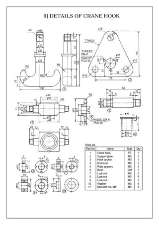
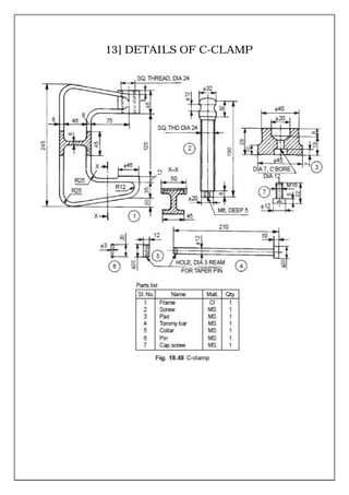
1 1 C-frame CS. Assembly Drawings must provide sufficient information to enable the assembly of a component. Name of part Material Notes Q.
2 Clamp or compression coupling. PDF 19 Kb. WEB-022-COMBINED_13pdf Schedule drawing for DN8 ¼ T bodies with hygienic clamp ends complete with top works options Page 1 - Body Only Details Page 2 Valve Assembly Details.
10 individual solid 3D parts 2D Inventor assembly DWG drawings 2 sheets in 1 Inventor DWG files 3D STEP 3D STL 3D DWF 3 files zip file 35 MB. Irreversible connection with excellent mechanical strength Fast and simple installation requires only a hammer No special training required Low resistance connection Provides a visual indication of completed connection Allows for T or pass-through connections. 1 5 Jaw Steel 1 4 Pin MS.
Assembly Drawings must have a number of views to show how parts fit together. 2200-60 Sheet 1 Sheet 2 Sheet 3-911228. Laboratory Project Instruction Drawings.
1 2 Handle MS. Problem 164 Working drawing metric PARTS LIST. Prepare a complete set of working drawings with all of the detail drawings on one sheet and the assembly drawings and parts list on another sheet.
CATALOG FOR CLAMPS FOR CLAMP HUB CONNECTIONS. These clamps are often used in welding jobs and woodworking projects. 1 3 Collar MS.
Item Post Date Author. C-clamp is used to hold a component for further work such as inspection or working on itThe work is clamped between the face of the frame and the pad mounted on the screw. Section views to show how parts fit and to eliminate hidden detail.
1 6 Cap screw MS. It is also known as split muff coupling. SOLIDWORKS 2013 June 25th 2017 C-Clamp.
Publish time 2014-09-01 1640. Interested in Vice Clamp Assembly drawing - Assessmentpdf Bookmark it to view later. It is required to design a C-clamp for holding the jobs on the shop floor limiting dimension of the job are as follows Hmax 150 mm Wmax 150mm The maximum clamping force required to hold the job is 10kN.
View C-Clamp-Assembly-Drawing-3of4pdf from ENGR 464 at San Francisco State University. Free CADBIM Blocks Models Symbols and Details. No Name of the component quantity Material 1 C-frame 1 Cast-steel grade 26-52 2 Screw 1 Steel 45C8.
C-Clamp Assembly Laboratory Project Instructions. Free CAD and BIM blocks library - content for AutoCAD AutoCAD LT Revit Inventor Fusion 360 and other 2D and 3D CAD applications by Autodesk. Prepare a complete set of working drawings with all of the detail drawings on one sheet and the assembly drawings and parts list on another sheet.
C-Clamp Assembly Screw Swivel Details of. 21 TITLE C-CLAMP ASSEMBLY DRAWING Ø4. You can exchange useful blocks and symbols with other CAD and BIM users.
The clamp is manually operated fSr. The complex beta clamp is shown in the following AutoCAD figure with parameterized sizes. 3600 Ø36 Ø20 2610 Ø32 M8 2X45 20 Ø10 6 12 Ø16 976 2 JAW SCALE.
16 QTY NAME PIN BODY SCREW SWIVEL SR 24 BOTH ENDS 102 72. Engineering Drawing And Design 5th Edition Edit edition Solutions for Chapter 15 Problem 5P. Other Related Materials Laser Material Processing 2nd edition notes 358 Condition Monitoring and Assessment of Power Transformers Using Computational Intelligencepdf 218 19BME0815 MD LABpdf 47 Screw Jack assembly Drawing v1pdf 3 Kraakman_1rtf 77.
Started from the complex clamp form. Use this sturdy C-clamp when you need a firm hold on your metal fabricating or woodworking projects. Up to 6 cash back LEGAL NOTICE DRAWING NOT TO SCALE ALL DIMENSIONS ARE NOMINAL PRODUCT PROTECTED BY ONE OR MORE US PATENTS SOLARMOUNT PART ASSEMBLY 10262017 PRO SERIES BONDING CLAMPS REVISION DATE.
WEB-023-COMBINED_13pdf Schedule drawing for DN8 ¼ with DN15 ½ branch end T bodies with hygienic clamp ends. Use multiview projection for view layout. Files 33 C CLAMP ASSEMBLY all parts Renderings Folder March 23rd 2014 c clamp assembly ggif gif April 6th 2016 c clamp picpdf pdf April 14th 2014.
In this case the muff or sleeve is made into two halves and are bolted together as shown in Fig. It consists of C-shaped jaw clamps and tightens the workpiece by applying pressure to the lever. Vice Grip Locking C-clamp.
The halves of the muff are made of cast iron. The locking clamps are ideal for quick use because it has a one-handed design. SOLIDWORKS 2014 STEP IGES Rendering March 18th 2019 Gokart Knuckle.
16A Clamps includes assembly drawings sizes available parts description and part numbers how to install plus a Hub Identification Worksheet a Clamp Identification Worksheet WOODCO USA API 16A License Certificate and DNV Type Approval Certificate. PDF 29 Kb. This industrial C-clamp is made of heavy-duty cast iron with a machined steel screw for optimal durability.
Dimensions to indicate range of motion or overall size of assembly for reference purposes. Assemble the following parts and Draw full sectional view of the assembly for the following. - 22 - 7 Screw rode MS.
Hammerlock Ground Clamp created on. STEP IGES November 4th 2018 c mount. One of the most popular styles of toggle clamps solid bar allows fixed location of spindle by welding bolt retainer at desired position u-bar allows spindle to be located anywhere on bar length flanged bases provide optimum holding pressure t-handles provide greater clearance for machines all clamps include spindle assembly all te-co.
DESCRIPTIONS M - A 0 1 PRODUCT LINE. Description of Kant Twist Clamp plans PDF and DWG 3D CAD models 3D Inventor 2014 assembly 2D DWG files complete set of documentation zip file 77 MB main assembly contains. CAD blocks and files can be downloaded in the formats DWG RFA IPT F3D.
Working Drawing Metric Assembly Name C Clamp Specif Chegg Com

C Clamp Assembly All Parts 3d Cad Model Library Grabcad

C Clamp Assembly

Pin Em T
Assembly And Details

Assembly And Details
2

Assembly Drawing Of C Clamp Youtube
0 comments
Post a Comment